![]() The Museum of HP Calculators
The Museum of HP Calculators
Customize this advanced new handheld calculator by plugging in extra memory, a magnetic card reader, a printer, and application modules. You can reconfigure the keyboard, too.
by Bernard E. Musch, John J. Wong, and David R. Conklin
THE MOST POWERFUL personal handheld calculator that Hewlett-Packard has ever designed, the new HP-41C, has over 130 preprogrammed functions and many advanced features, including a continuous memory that retains its information when the calculator is turned off, an alphanumeric liquid crystal display with status annunciators, a full alphanumeric keyboard that can be customized to fit user needs, and sophisticated but simple programming, including advanced editing, local and global labeling, specific loop control, flexible indirect addressing, and expanded decision-making capabilities.
In addition to these standard features, the HP-41C can become a powerful calculating system by means of options that can be connected to the basic machine through four ports on the top.
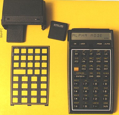
The HP-65, introduced in 1974, and the HP-67, introduced in 1976, were distinguished by electronic and mechanical features that represented an evolutionary follow-on to the HP-35, HP's first handheld calculator. They had numeric LED (light-emitting diode) displays and P-channel MOS (metal-oxide-semiconductor) circuitry. The HP-41C represents both an evolution of capabilities and system architecture and a significant departure in technology and configuration. The HP-41C uses CMOS (complementary MOS) circuits throughout and has an alphanumeric liquid crystal display. The configuration of the HP-41C is very much like a computer system. The handheld calculator is part of a distributed system that can include add-on semiconductor memory devices, a mass memory device, and a hard-copy output device. Fig. 1 is a picture of a system that includes the HP-41C Calculator, the 82106A Memory Module, and the 82104A Card Reader.
One of the most unusual features of the HP-41C was developed in response to the distributed nature of the system. It is the concept of USER mode and the capability for the user to completely reconfigure the calculator's keyboard.
USER mode can be best understood by considering the dilemma of where to put a key labeled PRINT on a machine that may or may not have a peripheral printer attached. For the user with the printer, the PRINT label should be in a prominent place, most likely on a keytop. For a user without a printer, putting a PRINT label on a keytop is a waste of a valuable commodity, a primary key.
A related dilemma is the proliferation of functions in this kind of system compared to the limited and relatively constant number of keys and surfaces on which to inscribe the nomenclature for these functions. The traditional solution has been to provide multiple shift keys and nomenclature in several colors to access various functions with each key. With USER mode, the solution is to provide only frequently used functions on the keytops and keydeck, and a single shift key. The front slopes of the keys are reserved for the alphabet and characters for alpha mode, and a procedure is provided to assign any function--mainframe, plug-in, or user-generated--to any key, primary or shifted (see user mode). The user-assigned keyboard configuration is maintained while the calculator is off, so that it need not be reentered each time the calculator is turned on.
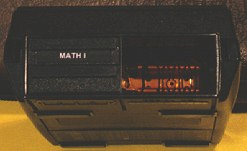
A second major feature of the HP-41C is the alphanumeric display. Fig. 2 is a picture of the display showing its salient features. The uses of the alpha capability include input prompting (e.g., KEY IN COST) as well as output labeling with variable names and units (e.g., X = 23.75 KM).
Prompting also extends to the key functions. Pressing any function key down and holding it will display the name of the function in the display for approximately one-half second. When the key is released, the function is executed. If the key is held down beyond the one-half second time period, the key nulls (i.e., is not executed). If the calculator is in the USER mode and the key has been reassigned, the function that is displayed and subsequently executed is the user's assigned function, not the one preprogrammed into the machine.
Additional uses of the alpha capability include displaying the program steps in program mode with the actual function name, and the generation of explanatory error messages, such as NONEXISTENT in response to an attempt to address a nonexistent register and DATA ERROR in response to an attempt to perform a mathematically impossible operation such as division by zero.
Providing a useful alphanumeric capability consistent with a conceptual extension of the HP-65/67/97 operating system was an interesting challenge. The solution consisted of providing an alpha register separate from the user's addressable memory and the operational stack. This register is capable of holding up to 24 alpha characters. Pressing the ALPHA key on the keyboard causes two things to happen: the contents of the alpha register are displayed, and the keyboard is converted into an alpha entry keyboard using the character set printed in blue on the front slope of the keys. Various functions in the machine's function set enable the user to manipulate and view the contents of the alpha register both from the keyboard and/or under program control.
The third area of distinction for the HP-41C is the capability of expanding the system's hardware using the four I/O ports on the top of the calculator (Fig. 3). The calculator's system bus is accessible at the I/O interface. This enables the user to expand the system by plugging in any device capable of interfacing to this bus. For example, add-on ROM (read-only memory) can increase the function set of the machine with programs written either in the machine's operating language or as sequences of user instructions. Plug-in RAM (random-access read/write memory) can expand the user's storage space for data and programs. Peripheral devices can be added to the system, with each device's function set contained in the ROM associated with the device itself. Thus, the user only pays for the capability to drive any peripheral when the peripheral is actually purchased. As of this writing, available peripherals include a magnetic card reader and a thermal printer, with an optical bar code reader due to be available in early 1980. Detailed descriptions of the first two devices are included in other articles in this issue.
A close look at the HP-41C architecture reveals an evolutionary design with close ties to the HP-351 and HP-212 families. In fact, the system timing is compatible with the HP-21 and much of the instruction set is very similar. The decision to stay with this familiar architecture allowed faster development and use of an existing circuit pioneered in the HP-25C.
Despite similarities in the architecture, there are many enhancements that make the HP-41C a much more powerful machine. Added features include a 2x improvement in operating speed, address expansion to 64K 10-bit words of ROM and 7K bytes of RAM, extensive I/O support with new peripheral instructions, a new display structure, and special power on-off controls. The chip set of the HP-41C includes one CPU (central processing unit), five data storage chips, three ROMs, and two display drivers, all CMOS, and one bipolar circuit. Fig. 4 is a block diagram of the system. With the exception of the display drivers, all the electronics are mounted on a single four-layer printed circuit board.
The calculator hardware can exist in any of three power modes. The first mode is the SLEEP mode. All of the circuits are inactive, but are biased on by the battery to sustain the continuous memory, consuming only a few microamperes of current for the entire calculator. When the unit is turned on, it enters the RUN mode. The clocks are running, instructions are executed, data is transferred, and the display is initialized and enabled. Under software control, the calculator transfers to a STANDBY mode in which the clocks and CPU are stopped. Only the display and the power supply remain active, and timing is controlled by the internal oscillator in the display driver. The RUN mode is activated whenever a key is pressed, and the calculator returns to STANDBY mode between keystrokes. If there is no input activity for approximately ten minutes, the display driver fumes out and shuts off the system altogether and the calculator is again in SLEEP mode.
The CPU is one of eleven CMOS circuits inside the HP-41C that were all developed and are fabricated within Hewlett-Packard. In the design process, various computer-aided design tools were used for logic and circuit simulations, digitizing, and design rule checks to provide faster development and assure more accurate and reliable circuits.
Inside the CPU there are five working registers (A, B, C, M, and N), one 8-bit register, one 14-bit status register, two pointers, and four subroutine return registers. The CPU supports 16 bits of ROM address, 10 bits of data register address, 56 keys with two-key rollover capability, 14 flag inputs and eight flag outputs. In the HP-41C, the flag output line is dedicated to driving the audible beeper.
In addition to these addressing and register capabilities. other CPU enhancements include new peripheral instructions to meet I/O demand, software-programmed on-off logic, automatic reset circuitry, and a new instruction to read ROM contents as data. The new instruction, CXISA, is especially useful for reading lookup tables, application ROMs, and ROM checksums.
There are five data storage circuits, each containing 16 56-bit registers of RAM (random-access memory). One of these circuits is allocated for internal storage, including the stack, display register, program pointers, and so on. The other four chips provide the user with 64 registers that can be partitioned between data and program memory at a rate of seven bytes of program per register.
In addition to the internal data storage, the HP-41C allows 16 more data storage circuits to be plugged into the system, four in each port. The I/O ports each have two pins that provide port address information to the plug-in memory modules. The memory modules are all identical and any number of them {up to four) can be in the system at any time. The only restriction is that the memory modules have to occupy ports starting with the lowest port number to provide a continuous program storage space.
The display system consists of a 12-character 14-segment liquid crystal display and a display driver hybrid that holds two display driver circuits. These are sandwiched together with connectors and clips. There are 75 connections between the LCD and the hybrid and 15 connections to the logic board.
The display is multiplexed three ways by scanning the three row lines on the backplane of the LCD and presenting the column information in parallel to all characters. An LCD segment is considered on when the rms voltage difference between that row and that column exceeds a certain on threshold, and off if this voltage difference is below a certain off threshold. The drive waveforms use a four-level scheme that provides optimum on and off rms voltage differences of 2.1V and 1.1V, respectively. Fig. 5 shows the drive waveforms required to produce letters H and P. The rms values are computed by averaging the squares of the row-column differences over the six time periods shown. In letter P, for example, segment 14 sees an rms voltage difference between row 1 and column 4 of:
sqrt{1/6 * [(1.1-0)2 + (3.3-2.2)2 + (1.1-2.2)2 + (2.2-3.3)2
+ (0-1.1)2 + (2.2-1.1)2]} = 1.1V
Thus segment 14 is off.
There are two identical display driver circuits, each driving six characters of the display. The two chips act as stand-alone peripherals to the system, with all controls, registers, ROM, buffers and drivers built in. The two circuits are connected in a chain, with information passed back and forth between them. To the system they look like a single 12-digit driver. The chips may be cascaded beyond two to handle systems with larger displays.
Information for each character is stored as a 9-bit string. Seven bits are used for the character's ASCII* equivalent--only 80 characters are decoded and displayed--and two bits are for the punctuation field. There is a separate bit per digit for the annunciators. The data from the CPU can be sent in 9-bit, 8-bit, or 4-bit (for numerics) fields in single-character or multicharacter form, from left or right side. The display can also be shifted left or right one digit at a time. All the column data is updated each time new information is sent and the decoded outputs are buffered in a three-bit shift register for each column. This is necessary because the columns are scanned at a slow rate; it also allows the display to be system-independent during STANDBY mode.
The HP-41C is powered by four N-size alkaline batteries with supply voltages ranging between 6V and 4V. Although CMOS can operate down to the 4V level, the speed would be greatly reduced. To optimize performance and provide LCD drive voltages and several other analog functions, a custom bipolar circuit was designed to perform the power supply functions.
The design goals for the bipolar circuit were to provide extremely low power and highly efficient operation. This circuit follows the three modes of calculator operation. In SLEEP mode, the CPU disables an input control pin, which shuts off all bias current to the internal circuits. In this mode, the chip draws less than 1 uA of current. In STANDBY, the chip is active, providing the 6V and LCD voltages, but at very minimal current. In RUN mode, the supply delivers as much power as needed by the system and its plug-ins up to 20 mA.
There are two internal references inside the power supply circuit, one for the 6V and one for the LCD voltages. The 6V supply is constant for a wide range of battery voltages and the full range of loading conditions. Outputs of 3.3V, 2.2V, and 1.1V are generated and held to very tight tolerances to provide good contrast and viewing angle for the display. These voltages also have a negative temperature coefficient of -20 mV/degree C to compensate for the LCD threshold change with temperature. There is a low-battery detection circuit that signals the CPU to activate the BAT annunciator when the battery is weak. The bipolar chip also generates a handshake signal that indicates to the CPU that the system voltage is adequate to start the rest of the circuits.
The HP-41C contains 12K words of system ROM (read-only memory), partitioned into three ROM chips with 4K words of 10 bits in length. That is 16 times more ROM than the HP-35 and more than twice that of the HP-67.
There are 16 bits of address field. The four upper bits are used as a chip-enable code to select one of 16 ROM circuits. The system ROM chips occupy the lower three addresses with peripherals filling in above them. The eight upper ROM locations are reserved for the plug-in application modules. With the two port address lines controlling bit 13 and bit 14 of the ROM address, the system can accommodate four plug-in application ROM modules at the same time, each containing one or two ROM circuits. An application ROM takes on the physical address of the port it is plugged into, but this is invisible to the user; the ROM operates in the same way in all four ports. Since different application ROMs can use the same physical address at different times, the number of possible application ROMs is not limited by the hardware.
The basic functions of the mainframe microcode may be seen in the flowchart in Fig. 6. The processor goes into its STANDBY stage between keystrokes to conserve power. Pushing a key causes the microprocessor to wake up and begin executing instructions. Some simple tests are run to ensure that the contents of RAM have not been lost, and then the keyboard is interrogated to see which key was pushed. It is possible for a peripheral to wake up the processor without a key being pushed. In this event the operating system jumps to a standard entry point in each plug-in ROM to give the ROM associated with the peripheral a chance to service the peripheral. There are seven standard entry points in each plug-in ROM to facilitate polling the plug-ins under various conditions.
In contrast to earlier HP handheld calculators, the mapping of a key onto the corresponding function can be an elaborate process in the HP-41C. When the calculator is in USER mode, a bit map of all the key locations is examined to see if the user has explicitly redefined the key. If not, a test is made to determine if the key is one of the auto-assignable keys. If the key is auto-assignable, a local label search must be conducted in the current user program to see if the corresponding label exists. Only after these possibilities have been checked does the operating system map the key onto its default function.
The HP-41C allows the user to access a function that is not assigned to any key by spelling out its name. The named function may be a mainframe function, a function in a plug-in application ROM or peripheral, or an alpha label in user program memory. The firmware searches through user program memory, all plug-ins, and the mainframe, in that order. There are no mechanisms to prevent a user from spelling a label the same way as a ROM function name, but the order of the search guarantees that the user's function will be found instead of the ROM function. Within user program memory, the search is conducted backwards, starting with the last label in program memory and working toward the beginning of program memory. This tends to result in the most recently entered label being found when there are duplicate labels in memory.
The CATALOG function was included to remind the user of all the functions available at any time. The order of the catalogs reflects the alpha name search order: CATALOG 1 displays alpha labels in program memory, CATALOG 2 displays plug-in functions, and CATALOG 3 shows the complete list of mainframe functions. Tables of pointers in the mainframe and at the beginning of each plug-in ROM determine the order of the entries in CATALOGS 2 and 3.
CATALOG 1 displays alpha labels in order from the top of program memory to the bottom, that is, oldest first, the reverse of the search order. CATALOG 1 also displays END statements in program memory, so that the user can tell which labels are in the same program. When CATALOG 1 executes, the user program counter is moved to each label or END as it is displayed; this allows access to programs that contain no alpha labels.
Alpha labels and ENDS are linked together in a chain. Each label or END contains a pointer to the label or END preceding it in program memory. This chain is traversed in its natural order when a search for an alpha label is conducted. When CATALOG 1 is executed, the firmware runs up the label chain to its end, counting the number of links. The final entry in the chain, which is at the top of program memory, is displayed first. For successive entries in the catalog, the counter is decremented and the chain is traversed again up to the link corresponding to the counter.
Operations on user program memory were particularly challenging to implement on the HP-41C. The processor speed, although fast in comparison to previous HP battery-operated calculator processors, is still very slow in absolute terms. The speed problem was compounded by potential memory configurations up to 10 times larger for user programs than on the HP-67. This combination of factors rendered the traditional methods of editing user program memory and searching for labels in user program memory prohibitively slow.
On the HP-67 or HP-97, when a step is inserted into the user's program, the remaining steps are moved down one byte at a time. On deletion of a step, remaining steps are moved up to fill the gap. Memory maintenance on the HP-41C, however, is closer to disc file maintenance than to the method used in the HP-67. When a step is deleted from an HP-41C user program, a null code is inserted in its place and no steps are moved. When a step is inserted, an examination is first made to determine whether there are nulls at the desired location that can be overwritten. If not, then seven bytes are made available by moving the remaining program steps down by one full register. The register move operation is intrinsically faster than the byte-by-byte move made on the HP-67. If several steps are to be inserted at the same place, register moves will generally only be necessary on the first insertion. Succeeding steps are inserted into the extra space created by the first insertion. An occasional PACK operation is necessary to reclaim randomly distributed nulls. When the HP-41C runs out of room, it PACKS automatically. The user can also invoke the PACK function explicitly.
In the HP-67, each time a user label is referenced by a GTO or GSB instruction, a linear search is made through the entire user program memory to find the label. The time spent searching for labels often represents a significant fraction of the execution time for HP-67 programs. On the HP-41C, several techniques have been used to minimize label search time. The HP-41C has two classes of labels: global alpha labels and local numeric labels. The END function on the HP-41C is used to divide user program memory into independent program spaces. When a reference is made to a local label, the search for the label is conducted only in the current program space, thereby shortening the search time. Once the target label is found, its location is stored with the GTO that referenced it; in other words, the GTO is "compiled." The search is eliminated altogether on subsequent executions of the GTO function if the program has not been edited in the meantime. Global alpha labels are used for references across program space boundaries. The alpha label chain described above serves to speed up the search for global alpha labels.
The concepts of global versus local labels and separate program spaces, although not new to computer programmers, are important advances for a programmable calculator. A user can always write a new program without worrying about what numeric labels have been used in programs already in the machine, simply by creating a new program space. Users can similarly exchange and use each others' subroutines without regard for conflicting numeric labels. Moreover, the global alpha labels used to name programs can be up to seven characters in length, long enough to be meaningful and memorable.
A number of techniques were used in the HP-41C firmware to allow for plug-in application ROMs and peripherals. First, all functions in plug-ins are accessed by a logical ROM ID and function number, rather than by a physical address. This allows plug-ins to work without regard to which of the four ports they are plugged into. When such a function is executed, the firmware searches through all of the ports until it finds the ROM bearing the ROM ID of the function. Second, provisions have been made to allow plug-ins to seize control of the CPU at certain times, such as just before the CPU goes into STANDBY mode. The firmware polls all of the plug-ins whenever any one of seven events happens. Third, some subroutines are included in the mainframe specifically to permit the use of address-independent microcode in the plug-ins, which may take on the physical address of whichever port they are plugged into. Fourth, a number of subroutine calls to the printer ROM (which has a fixed, rather than port-dependent, physical address) are embedded in the mainframe firmware to permit the intimate interaction between printer and keyboard that was pioneered by the HP-97. In this case the firmware takes advantage of a feature of the CPU that causes an immediate return to be executed whenever a subroutine jump is made to a nonexistent ROM. This same feature is also used for the diagnostic ROM. Whenever the CPU first turns on, the firmware executes a subroutine call to a fixed-address diagnostic ROM. If the diagnostic ROM has been plugged into one of the HP-41C's ports, it takes over; otherwise, control is returned to the mainframe microcode. (The diagnostic ROM is a tool developed to help HP service technicians troubleshoot a malfunctioning HP-41C. This ROM is not available to customers.)
Those responsible for the integrated circuits used in the HP-41C are Donald Reid for the CPU, Henry Koerner for the display driver, and Peter Yu for the ROM. Major contributors to the mechanical package include Dave Scribner, Jerry Steiger, Rick Nelson, and Bill Grace. Rich Whicker contributed to the development of the display. Bill Egbert was the guiding spirit of the HP-41C firmware. Other members of the firmware team were Steve Chou, Gaye Daniels, Ray Davis, Greg Filz, Bob Worsley, and Dennis York. The math algorithms were adapted for the HP-41C by Dennis Harms and Tony Ridolfo. Ed Liljenwall was the industrial designer. Roger Quick managed the project single-handedly in its early stages. Special thanks must go to Max Schuller, whose experienced hand stabilized our course during the final push into production. Bernard Tsai was and is our production engineer. Ray Tanner wrote the HP-41C manual. In addition, there were many individuals outside the product development team without whose able assistance we could not have succeeded.
1. T.M. Whitney, F. Rode, and C.C. Tung, "The 'powerful Pocketful': an Electronic Calculator Challenges the Slide Rule," Hewlett-Packard Journal, June 1972.
2. M.J. Cook, G.M. Fichter, and Richard E. Whicker, "Inside the New Pocket Calculators," Hewlett-Packard Journal, November 1975.
*American Standard Code for Information interchange
Bernard E. Musch
Bernie Musch's HP career parallels the history of HP personal calculators He joined the company in 1970 and helped design the HP-35, the first HP handheld calculator. He contributed to the HP-55 and HP-65, served as project manager for the HP-91, and since 1976 has been section manager for various handheld calculators including the HP-41C. He's authored several papers, most recently on the calculator business, and generated several patents in the areas of mechanical design and calculators. He received his BSME degree from Lehigh University in 1964 and his MSME and PhD degrees from Stanford University in 1966 and 1970. Born in Baltimore, Maryland, Bernie is married, has two sons, and lives in Corvallis, Oregon. He's interested in music and sports, is active in the American Youth Soccer Association, and serves as scoutmaster of the local Boy Scout troop.
John J. Wong
Mainland China is the birthplace of John Wong, who came to California in 1963 and to Hewlett-Packard ten years later, following his graduation from the University of California at Berkeley with a BS degree in electrical engineering. John developed several integrated circuits for the HP-25, HP-25C, and HP-27 Calculators before becoming project leader for the HP-41C. He later took over responsibility for all of the HP-41C electronics as project manager. John, who lives with his wife and two children in Corvallis, Oregon, spends his spare time doing electronics projects at home and exploring his interest in photography and hi-fi stereo.
David R. Conklin
Dave Conklin started his career with HP in 1975, then resigned to move to Corvallis, Oregon, only to join HP again when the calculator division moved to that city. While with HP's Santa Clara Division, he was a quality assurance systems engineer and a programmer on the 5420A Digital Signal Analyzer. At the Corvallis Division, he first worked with the firmware team for the HP-41C, then became project manager for the 41C follow-ons in 1979. Dave's BA degree in mathematics is from the University of California at Berkeley (1967), and his MS degree in computer science was completed in 1975 at the University of Santa Clara. Dave has also worked in programming and systems analysis for nuclear power plants and computer-controlled sawmill systems. A member of ACM and IEEE, Dave is married and lives in Corvallis. Raising mules and applying programmable calculators to problems in pharmacokinetics are among his leisure time activities.
The procedure for the user to redefine a key on the HP-41C keyboard is simple and straightforward. If a peripheral device or application module is plugged into one of the I/O ports of the HP-41C, the user can execute the CAT 2 (Catalog 2) function to review the plug-in's repertoire of available functions. The listing below shows the function set of the printer.
         CAT 2

-PRINTER-      PRP
ACA            (T)PRPLOT
ACCHR          (T)PRPLOTP
ACCOL          PRREG
ACSPEC         PRREGX
ACX            PR Σ
BLDSPEC        PRSTK
LIST           PRX
PRA            RECPLOT
(T)PRAXIS      SKPCHR
PRBUF          SKPCOL
PRFLAGS        STKPLOT
PRKEYS
To assign, for example, the PRX (Print X) function to the R/S key location:
User Keys In Display ShowsASN ASN __ ALPHA ASN __ ALPHA PRX ASN PRX __ ALPHA ALPHA ASN PRX __ R/S ASN PRX 84
The underscore prompts for additional information, the alpha annunciator comes on to indicate that the keyboard is in alpha mode, and the 84 indicates that the key being assigned is the 4th key in the 8th row.
Now that the key has been reassigned, the user may invoke the PRX function merely by pressing the USER key (displaying the annunciator USER) and then pressing R/S. The USER key may be thought of as a permanent shift key that shifts every key from the normal definition to the user's own key definition.
If the R/S key is pressed and held in the USER mode, the mnemonic PRX is displayed as a reminder of what function is to be executed; to void or NULL out its execution the user merely holds the key down for more than 1/2 second. In this way the current redefinition of the keyboard may be reviewed without disturbing the contents of the machine's registers.
If the printer is now unplugged from the calculator and the R/S key is pressed and held the message XROM 29,20 appears in the display indicating that a function that is in a ROM eXternal to the machine has been assigned to that key. The numbers indicate that it is the 20th function of device number 29 (the printer). Of course, both the name and the nature of XROM function 29,20 is unknown to the calculator as long as the printer module remains unplugged. Any attempt to execute an XROM function will result in NONEXISTENT in the display. The printer may be plugged in again (into any port) and the PRX function will reappear, assigned to the R/S key.
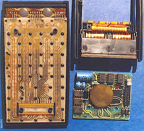
The design of the HP-41C borrows heavily from previous HP calculator designs. The contours of the case recall the classic HP-35. The mechanical design is similar to the HP-21, using four major subassemblies: display, top case/keyboard, logic board, and bottom case.
The display assembly, Fig., [These pictures actually show an HP-41CV interior.] required the most new mechanical design work, primarily because of space restrictions, but also because the HP-41C is HP's first liquid crystal display product. Because the alphanumeric LCD requires so many connections, a display driver hybrid is connected directly to the LCD through elastomeric connectors on the long sides of the display. Registration of the hybrid to the LCD is established by a plastic locator bonded to the LCD. The assembly is held together by two spring clips that provide the required contact pressure and protect the glass LCD from impact. The display assembly is attached to the keyboard by a comb of contacts that are reflow soldered to the hybrid and keyboard (Fig.).
The keyboard is heat-staked to the top case as in the HP-21 and uses metal discs for key contact and tactile feedback as in the HP-19C. Removable overlays and transfer labels keep track of redefined keys. Using a momentary-contact ON/OFF circuit eliminates the need for slide switches and the special plating they require.
The logic board, Fig., makes contact to the keyboard through another elastomeric connector, again because of space restrictions. Contact pressure is maintained by two nuts driven over the top-case screw bosses. A spacer, sonic welded to the bosses, establishes the logic board height and prevents overdriving of the nuts from affecting key feel. The piezoelectric beeper is mounted to the logic board to facilitate assembly and repair. Foam tape presses the beeper against the bottom case, which acts as a sounding board.
The bottom case contains the I/O ports and the one-piece battery case/door. The battery springs are used as jumpers, to apply contact force, and to hold the case in place, as in the HP-21. There are two small cantilever springs to hold the cells in place while outside the calculator. The battery and I/O contacts are on a flexible printed circuit that is wrapped around and heat-staked to a plastic contact frame. The batteries make contact at the ends of four small ribs. The I/O contacts are made on the tops and bottoms of four larger ribs, like edge connectors on a hard printed circuit board. A piece of polyurethane foam held in the top of the contact frame presses the flexible circuit against the keyboard to make contact there. Four screws attach the bottom case to the top case, trapping the contact frame and the center case, a cosmetic piece, between them.
Gerald W. Steiger
Jerry Steiger is a native of eastern Oregon and a graduate of the University of California at Berkeley, where he received his BSME degree in 1970 and his MSME degree in 1972. After three years doing product design for toys and label guns, he joined HP's Advanced Products Division (now the Corvallis Division) in 1975 to assist in the development of the HP-10 and HP-19C printers. For the HP-41C, he was the primary mechanical designer and worked on production engineering. Married and living in Corvallis, Jerry has a 2-year-old daughter and is interested in music, science fiction and fantasy, military history, wargaming, and downhill skiing.
![]() Go back to the HP Journal library
Go back to the HP Journal library
![]() Go back to the main exhibit hall
Go back to the main exhibit hall