by Craig Maze
LIQUID CRYSTAL DISPLAYS are used in calculators largely because of their inherent low power dissipation and low voltage requirements. Other factors contributing to their expanding use in calculators and portable instruments are the ease with which different character sizes and shapes can be produced inexpensively and LCDs' good visibility under conditions of high ambient lighting.
The display used in the HP-41C is a multiplexed, twisted nematic LCD with a twelve-character alphanumeric capacity. It operates from 0 to 45 degrees C with electrical compensation of the drive voltage to correct for LC property variations with temperature.
LCDs are optically passive in that they do not generate light to produce contrast. Operation of the device depends on the ability of the LC to rotate plane polarized light relative to a pair of crossed polarizers attached to the outside of the display. Rotation of the plane of polarization is a function of the applied field and decreases with increasing field or voltage. The following brief discussion of LC properties and display construction will serve to explain how a twisted nematic LCD works.
Nematic liquid crystals are ordered fluids whose molecules lie parallel to each other with their centers of mass randomly distributed. They are organic compounds and their molecules are rod-like in overall shape. The word "nematic" comes from the Greek "nema", meaning "thread-like." A thread-like pattern is observed when nematics are viewed through a microscope under polarized light. The difference between Nematic and ordinary fluids is illustrated in Fig. 1.
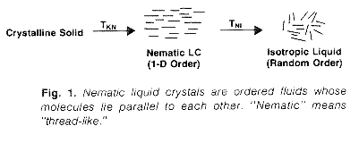
Nematic liquid crystals are formed by melting otherwise ordinary crystalline solids. Unlike most solids, which transform into isotropic liquids upon melting, a nematic liquid crystal passes into an ordered phase at temperature TKN Additional heating, to TNI the clearing temperature, will cause the nematic to undergo another phase transformation where molecular order becomes random. To an observer, the solid will transform into a milky, light-scattering fluid at TKN and then become clear at TNI. Cooling reverses the sequence of transformations.
Nematic liquid crystals have one-dimensional, long-range order, are uniaxial crystals, behave like liquids, and possess elastic properties. Two examples of commercially available liquid crystals along with transition temperatures and dielectric properties are shown in Fig. 2.
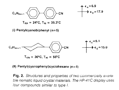
The HP-41C uses a mixture of four liquid crystals similar to type I of Fig. 2. Multicomponent mixtures are necessary because no single compound has an appropriate nematic temperature range for use in products. In the case of the HP-41C, the nematicrange is -10 to 60°C. Specified display operating temperature limits are always well within the nematic range. The ability of a display to perform at low temperature is usually limited by increasing viscosity and attendant slower on-off response, and not by freezing of the liquid. The upper bound results from highly nonlinear variations in LC properties with temperature, making compensation in the drive circuitry too complex.
To facilitate further discussion it is convenient to define a unit vector, called the director, which is parallel to the long molecular axis. LC structure and molecular orientation in a liquid crystal display can be discussed in terms of director orientation.
Dielectric anisotropy (Eparallel - Eperpendicular) is positive for LC materials of types I and II and for mixtures used in twisted nematic displays. The largest component, Eparallel, is parallel to the director. Three elastic constants can be defined for nematic substances and used to describe the forces required to displace the director from its equilibrium position. These constants are many orders smaller than elastic moduli of ordinary solids. Even though small, a static balance between elastic and dielectric torques arises when a field is applied to an LCD. This balance produces a well-defined molecular structure that determines the degree to which the plane of polarization is rotated in a display.
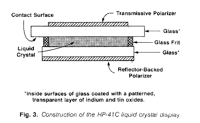
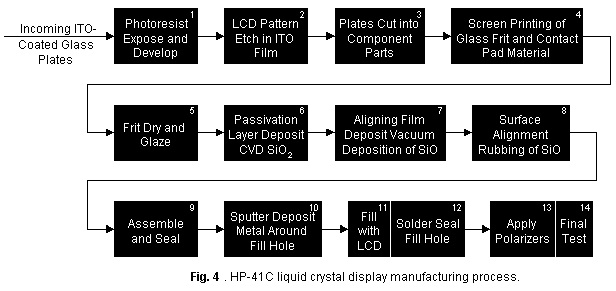
Construction of the HP-41C display is depicted in Fig. 3, and Fig. 4 is the process flow sheet. The display is a parallel plate capacitor with polarizers bonded to the external surfaces. The two glass plates are separated by about ten micrometres and sealed with a vitreous glass frit. Liquid crystal fills the space between the plates, and the molecules are oriented with their directors in the plane of the substrate. The directors are also aligned parallel to the axis of the polarizer attached to the outside of the adjacent glass. A 90-degree director twist results with nematic order producing a uniform change across the liquid crystal layer. This structure is shown in Fig. 5a.
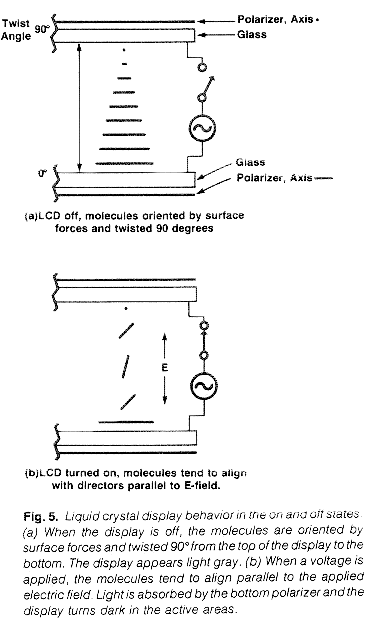
Light passing through the first polarizer rotates 90 degrees as it passes through the LC layer. As a consequence it is aligned with the second polarizer, passes through, reflects, and propagates out unattenuated. The entire display appears light gray as a result of polarizer and reflector tints. Application of a voltage across the LC causes the directors to rotate so they are parallel to the applied field. At a sufficiently high voltage, alignment is nearly parallel as shown in Fig. 5b. The 90-degree director twist is eliminated, for all practical purposes, and light propagating through the LC is absorbed by the second polarizer. Dark digits appear in the active areas.
Director tilt increases with increasing voltage, and as a consequence, contrast develops first at lower voltages at shallow viewing angles. As shown in Fig. 6, brightness decreases at lower voltages at a 40-degree viewing angle compared to the curve representing zero-degree behavior.
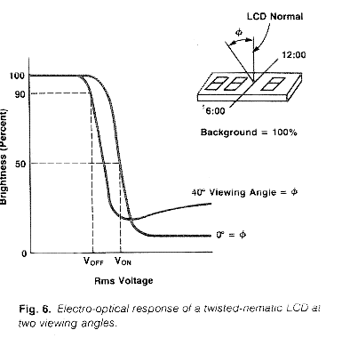
Multiplexed displays operate with voltage applied at all times. To be off, nonselected elements must be above 90-percent brightness, and for the HP-41C, this is required to extend over a 40-degree angle. These two factors define the rms off voltage, as shown in Fig. 6. Good viewing also dictates that brightness be 50 percent or less for selected elements over the same 40-degree angle, and this voltage is also shown in Fig. 6.
A small Von/Voff ratio is desirable for good optical performance for an LCD operating in the multiplexed mode. Proper selection of the LC material, care in LC surface alignment, and care in maintaining proper cell spacing all serve to maximize viewing angle and contrast for a given application.
Two separate groups have been involved in the development of LCD technology at HP. First, in Corvallis, thanks to Curt Sheley, Ed Heinsen, Paul Van Loan, Pat Shelley, and Earl Garthwait. At HP Labs credit goes to Fred Kahn, Hsia Choong, and Henry Birecki for their technical assistance over the past several years. Ed Kanazawa of Data Terminals Division and Sun Lu, formerly of HP, were also major contributors.
Craig Maze
A midwesterner from Galveston, Indiana, Craig Maze took his BS degree in chemical engineering from Purdue University in 1959, and later attended Iowa State University, where he earned his MS degree in 1967 and his PhD in 1970, both in chemical engineering. He joined HP in 1978 as a product engineer on the HP-41C liquid crystal display program, Author of 18 papers and named inventor on two patents, he worked in the fields of liquid crystals, polymer science, thermal analysis, surface chemistry, and computer modeling before joining HP. His professional memberships include the American Chemical Society and the American Institute of Chemical Engineers. He has spent two years in the U.S. Army and taught thermodynamics and chemical instrumentation at Arizona State University. Now a resident of Corvallis, Oregon with his wife and three children, two of whom are in college, Craig spends his spare time gardening, trying his hand at photography, and generally enjoying outdoor activities.
![]() Go back to the HP Journal library
Go back to the HP Journal library
![]() Go back to the main exhibit hall
Go back to the main exhibit hall