The original three members of the HP 9800 series (models 10, 20 and 30) all used the same basic underlying hardware. While these calculators and the HP 9100 are only 3-4 years apart in introduction dates, modern calculator users will find that 9800 series electronics to be much more familiar.
The HP 9800 series machines used an 8MHz 16-bit processor. The CPU was microcoded and could execute 75 different instructions. Microcode was stored in bipolar ROM (7 ICs were used to supply 256 28-bit words.) The instruction set was designed to resemble the HP 2100 series computers.
The processor had 4 main registers (A, B, E, and P). The P register was the program counter. The A and B registers were accumulators with A allowing binary or decimal operations and B allowing binary operations only. The E register was designed as a four bit extension to the other registers. It was used when shifting Binary Coded Decimal (BCD) data. There was also a fifth register named Q which contained the instruction being executed. Once this instruction had been fully decoded, Q was used as a scratch pad.
In addition to the bipolar ROM used for Microcode, n-channel MOS ROM was used to hold the calculator firmware. When the project started, printed circuit board ROM as used in the HP 9100 was still much less expensive than IC technology, but HP gambled (correctly) that MOS ICs were the wave of the future. The 4K bit ROM chips and the process to build them were developed at HP because commercially available devices didn't meet the needs of the calculators. The chips were organized as 512 8-bit words.
The memory system was designed so that "ROM blocks" containing specialized routines could be added to calculator. On the HP 9810, the first block added supplied the functions for 15 of the keys on the keyboard. The next two blocks controlled peripherals. On the HP 9820, each of three optional blocks provided functions for one of three sets of ten keys. The HP 9830 allowed 8 blocks to be added. However, since it had a QWERTY keyboard, blocks added keywords rather than key functions.
The HP 9800 series used Intel 1103 1K bit PMOS dynamic RAM ICs. Hardware was included to refresh the memory at least once every two milliseconds. Such chips didn't exist when the HP 9100 was introduced.
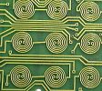
The keyboards had a printed circuit board transformer under each key. Each key had a metal disk and when this disk was moved closer to the coils printed on the circuit board, it changed the transformer's performance. This change was amplified by a comparator. This kind of keyboard was very reliable due to the lack of mechanical contacts.
The HP 9800 series used heavy duty sheet metal cases. These were lighter (though not as strong) as the HP 9100. Because of the denser packaging and greater speed (and therefore heat), a fan was added. All boards (even the power supply) plugged into edge connectors. The card ejectors were color coded to match the colored slot guides to eliminate assembly errors.
|
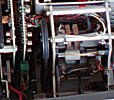
Picture of the interior of an HP 9810. One of its card cages has been partially removed for easier viewing. The ROM slots are just behind the display board. The open area behind the printer is for I/O expansion. |
|
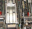
Picture of the interior of an HP 9820 |
|
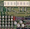
Picture of an HP 9820 display board. |
|
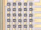
Close up on a single character of the 9820 display. |
|
Picture of the bottom of the HP 9820 keyboard. |
|
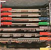
Picture of the interior of an HP 9830. The display is beyond the top of this picture. The area at the top right is where ROMS are inserted. The tape drive is at the top left. |
|
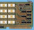
Picture of an HP 9830 board. |